
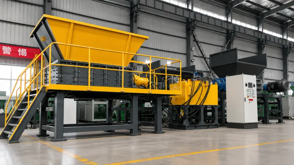
Hydraulic Shredders operate at the primary coarse shredding stage of plastic recycling plants. They use hydraulic motors to turn intermeshing alloy rotor shafts, shearing and crushing bulk feedstocks such as agricultural films, woven bags, large hollow drums, and heavy purgings.
Bulk scrap plastic enters the feed opening in varied forms. Baled film wraps tightly around rotor shafts, while heavy lumps and solid purgings produce severe mechanical shocks on engagement. In rigid mechanical drives, these shock loads transfer directly into gearbox teeth and motor rotors. A Hydraulic Shredder transmits power through fluid circuits, maintaining preset torque under stall resistance while dampening mechanical shock loads from the material.
Proper machine sizing depends on drive parameter matching and rotor configuration. Sizing assessments look beyond nominal motor power. Key verification parameters include pressure build-up speed, motor displacement at low shaft speeds, and tooth geometry designed for either flexible films or dense polymers. Correctly configured drives limit jamming, reverse cycles, and unbudgeted downtime, delivering consistent primary output to downstream secondary granulators and washing lines.
| Operating Condition | Primary Scrap Plastic Form | Hydraulic Drive Focus | Rotor Structure | Selection Criteria |
|---|---|---|---|---|
| Flexible Wrapping Materials | Agricultural film, woven bags, strapping | Medium-pressure, high-flow circuit with fast shaft speeds and quick forward-reverse response | Narrow alloy knife bodies, multi-hook edges, close knife clearance against comb-style counter knives | Stretchy materials wrap around shafts, requiring rapid shearing and dedicated clearing knives |
| Dense Thick-Walled Materials | Injection purgings, thick-walled pipe, solid rubber lumps | High-pressure, large-displacement piston motors for zero-speed peak torque and relief protection | Thick alloy knives, single or double-hook design, open bite-profile cutting chamber | High compressive and shear resistance requires focused tooth force to prevent bending deflection |
| Mixed Bulky Waste | Large packaging containers, mixed industrial scrap plastics | Load-sensing variable hydraulic system adjusting speed and torque to real-time cutting pressure | Staggered double-hook knife arrangement with hardfaced tool surfaces on heavy-duty knife seats | Wide swings in size and hardness demand automatic speed shifts and overload shock cushioning |
1. Load Surge Characteristics in Bulk Plastic Processing and Hydraulic Anti-Overload Mechanisms
Baled materials or loose stockpiles create erratic shock loads when dropped into the shredding chamber. Flexible plastics stretch under rotor pressure, wrapping around shafts and multiplying frictional drag. Solid injection purgings demand extreme cutting force the instant teeth make contact. Mechanical gear-driven systems rely on thermal overloads or variable frequency drives to trigger motor reversals under these conditions, and repeated starts and stops wear down switchgear and geartrains.
A hydraulic drive system uses a primary pump and low-speed, high-torque motors. When shafts stall on unshreddable items, circuit pressure rises to the relief valve setpoint. High-pressure fluid vents directly to tank, stopping rotor rotation while the drive remains fully engaged. This fluid coupling prevents gear tooth shearing and motor rotor-stator collisions.
The choice between hydraulic and mechanical drives depends on contamination levels and the share of dense purgings in the feedstock. Mechanical units work well with clean, single-origin hollow containers. When the stream contains unsorted industrial scrap, heavy polymer lumps, or tramp metal, a Hydraulic Shredder provides the required overload cushioning.
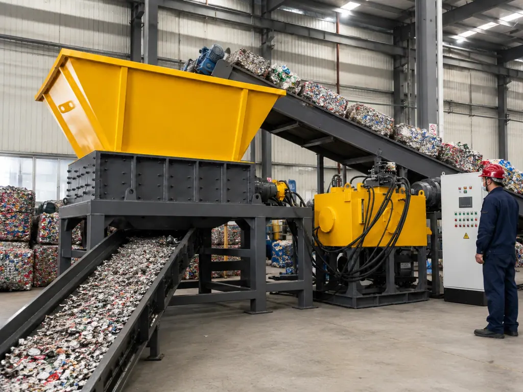
2. Sizing Low-Speed High-Torque Hydraulic Motors: Displacement and Working Pressure
Shredder cutting performance depends on system operating pressure and motor displacement. Motor displacement sets baseline shaft torque, while circuit pressure sets peak force limits against stubborn material. Configurations typically feature large-displacement radial piston motors that deliver continuous maximum torque down near zero speed, keeping rotors moving through dense sections without stalling out.
Variable pump controls must integrate with electrical controls. Thin-walled containers present minimal resistance, allowing the circuit to run at high flow and moderate pressure, turning the shafts faster to maximize throughput. When teeth strike solid polymer blocks and hydraulic pressure rises, the variable pump decreases displacement. This raises pressure to maximum operating limits, shifting the shafts into slow, high-force shearing.
Drive evaluations evaluate the ratio of stall torque to continuous running torque. Processing dense purgings demands high peak shearing force, requiring high-pressure circuit designs. For large hollow containers where resistance is lower, priority shifts to high-displacement, moderate-pressure circuits that run rotors faster to maintain tons per hour.
3. Hydraulic Shredder Rotor Configurations for Rigid Lumps and Wrapping Films
Rotor tooling determines whether material feeds reliably into the cutting zone. High-tensile film, woven bags, and strapping require multi-hook profiles with tight clearances between rotor knives and counter knives. Wide clearances allow thin film to wedge into shaft gaps without cutting. Multi-hook profiles catch and slice stretched film, working with comb-style counter knives to clear shaft roots and stop material wrapping.
Injection purgings, heavy pipe, and solid plate place heavy localized point loads on cutting edges. These applications require thick single-hook or double-hook knives, with fewer teeth per shaft to focus available torque on minimal contact points. Heavy knife bodies provide the bending resistance needed to handle lateral thrust during penetration, reducing chipped or broken teeth.
Rotor configuration depends on the physical form of the primary feedstock. Streams dominated by films and flexible fibers require thinner knife profiles, multi-hook teeth, and closely spaced counter knives. Feedstocks consisting mainly of thick purgings and heavy lumps demand wide knife profiles, large hook profiles, and an open cutting chamber that lets large pieces drop into the bite zone.
FAQ
- Why do injection purgings frequently stall plastic recycling lines, and how does a Hydraulic Shredder prevent this?
- Injection purgings have high density and irregular shapes. Conventional mechanical units often lack the instantaneous cutting force needed on impact, tripping motor overloads. Hydraulic Shredders run on low-speed, high-torque hydraulic motors. When teeth meet resistance, circuit pressure rises, and variable pumps adjust automatically to maintain maximum torque. If resistance reaches safety setpoints, fluid vents across relief valves, and the system reverses shafts before cutting again, avoiding gear tooth damage and motor burnouts.
- What knife shaft specifications prevent agricultural films and woven bags from wrapping in a Hydraulic Shredder?
- When handling flexible wrapping plastics, critical areas include knife thickness, tooth hook profiles, and clearances between rotor knives and counter knives. The configuration requires closely spaced multi-hook knives and comb-style counter knives with tight clearances to cut fibers cleanly. The hydraulic motor must also deliver fast reverse response at low speeds to shake loose wound material as soon as wrapping starts.
- Which downstream processing units typically connect to a Hydraulic Shredder in a Plastic Crushing & Recycling Line?
- A Hydraulic Shredder handles primary coarse shredding and bulk volume reduction, producing large shreds. Downstream lines typically feed this material into secondary granulators for particle size reduction. Magnetic separators or air classifiers remove metals and light contaminants before the shredded plastic moves to washing, drying, and extrusion pelletizing.