
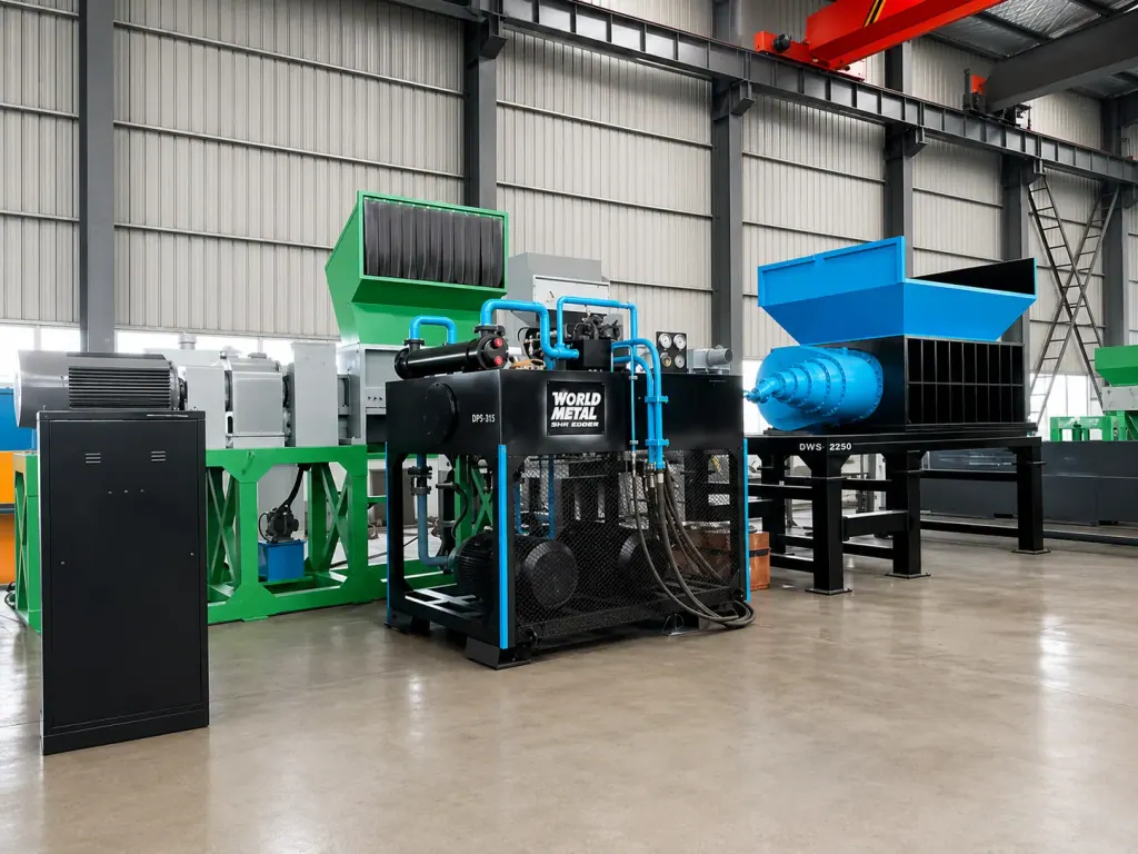
Hydraulic Shredders are standard primary units placed at the front of a Ferrous Metal Shredding Line. Driven by low-speed, high-torque hydraulic motors, alloy knife shafts shear bulky scrap steel and vehicle shells into uniform fragments for downstream magnetic separation and secondary milling.
Coupling electric motors directly to mechanical gearboxes creates severe shock risks when processing mixed light sheet, thick-walled parts, or bales. Instant stalls transfer direct shock loads into the geartrain, stripping teeth or burning out motors. Hydraulic drives transfer power through fluid, delivering full rated torque even when shafts are forced near zero rpm. If uncrushables enter the chamber, hydraulic relief valves release pressure immediately to clear the load.
Selecting equipment begins with calculating the peak shear force required by the maximum feed thickness. This force determines motor displacement and operating pressure, which then defines the cutting chamber structure and reversing protection thresholds to maintain steady feeding under heavy loads.
| Equipment Type | Feed Material | Process Stage | Selection Criteria |
|---|---|---|---|
| Hydraulic Shredder | Vehicle shells, industrial scrap steel, bulky structural parts | Primary volume reduction and coarse shredding | Low-speed, high-torque operation with automatic pressure-based reversing logic to resist heavy shock loads in mixed scrap feeds |
| Double-Shaft Shredder | Light scrap metal, mixed solid waste, white goods casings | Primary shredding and uniform size reduction | Intermeshed alloy knives delivering multiple shear cuts; requires gearboxes rated for alternating loads and sealed bearing assemblies |
| Hammer Mill | Pre-shredded scrap fragments, small domestic appliance scrap | Secondary milling and paint stripping | High-speed impact crushing using discharge grates for sizing; requires pre-sorting to remove heavy uncrushables upstream |
1. Hydraulic Drive Parameters and Torque Matching for Primary Shredding
Feeding mixed car bodies, metal bales, and structural sections creates steep fluctuations in tensile strength. Sizing the drive must not rely on average hardness values. Peak motor torque must reflect the instantaneous shear limit of the thickest structural member in the mix. Motor displacement and gear reduction ratios should prioritize linear cutting force at the bite point rather than free-run shaft speed.
When processing loose scrap and thin sheet metal, increasing oil flow raises shaft speed to accelerate volume reduction. Once the grab drops heavy structural sections or dense scrap bundles into the hopper, the primary pump strokes down displacement and lowers shaft speed. System pressure builds to nominal levels, applying high torque to shear the material apart. Sizing verification comes down to two operating indicators during continuous peak feeding: whether the cooling circuit maintains oil temperature within specifications, and whether the main relief valve opens repeatedly under load.
2. Cutting Chamber Construction, Shaft Center Distance, and Knife Alloys
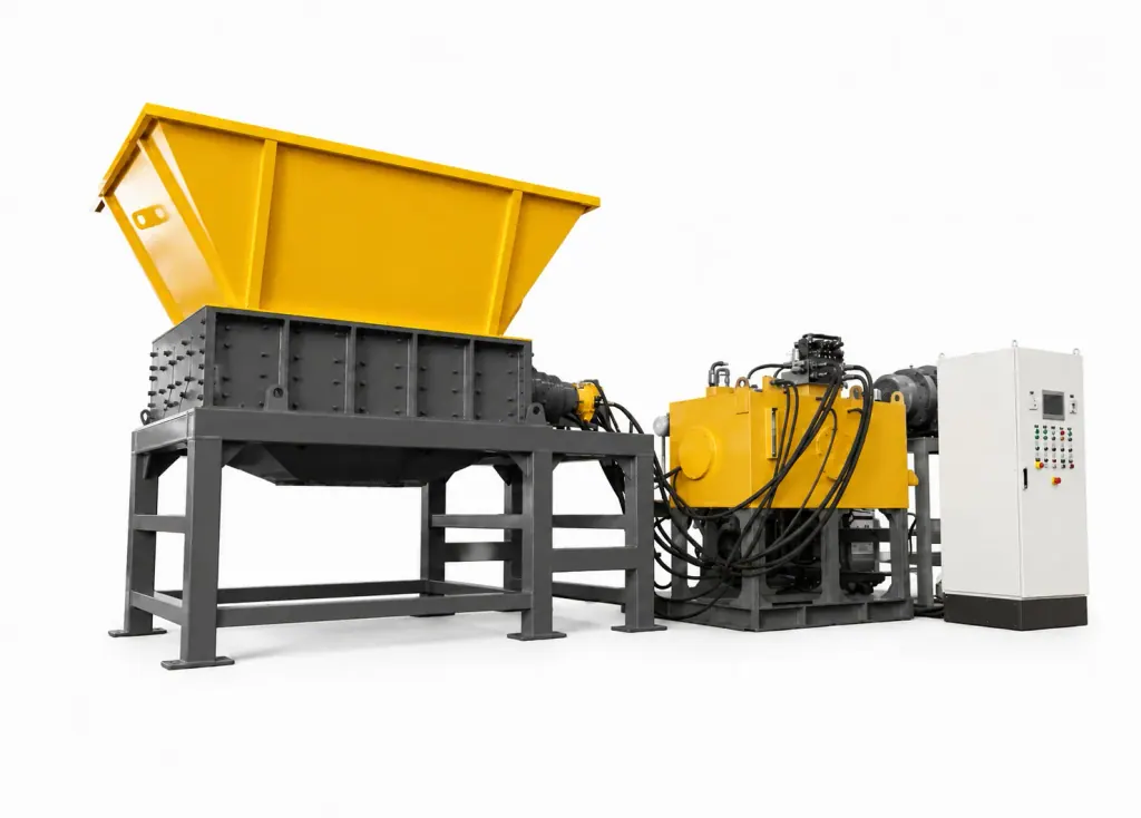
Primary shredding of heavy scrap exposes the cutting chamber to radial tearing forces and axial thrust. The chamber requires monolithic cast steel or heavy annealed weldments. Bearing housings must sit outside the chamber walls behind independent seals to stop abrasive fines, scale, and slurry from entering the roller bearings. Shaft center distances fix the cutting overlap. Setting shafts too far apart causes sheet metal to spin without feeding; setting them too close wastes power on redundant recutting.
When feeds consist mainly of vehicle shells and light pressings, multi-tooth wear-resistant alloy blades provide multiple piercing points to distribute tooth loads. For heavy pipe or structural sections, single-tooth or double-tooth profiles are required because their wider root cross-sections resist breakage during stalls. Clearances between spacers and counter knives should be checked once per shift to keep sheet metal from wedging between blades and deflecting the shafts.
3. Hydraulic Station Pressure Control and Anti-Jam Reversing Logic
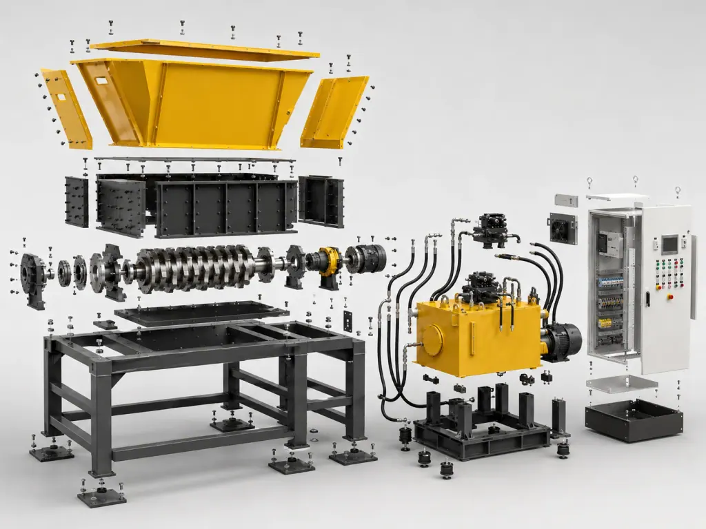
Solid quenched shafts or thick billets can enter the shredder unexpectedly. The hydraulic station relies on dual-stage pressure relief. A pilot-operated relief valve bypasses flow the instant the shafts lock up, preventing plastic deformation of shafts and housing. In parallel, the electrical control monitors pressure rise gradients via sensors, flagging solid obstructions as soon as the pressure curve steepens abnormally.
When circuit pressure reaches and holds at the relief threshold, the PLC signals proportional valves to reverse the shafts for one to two rotations. This action ejects the obstruction and repositions it before the drive resumes forward cutting. If multiple reversing cycles fail to pass the material, the system shuts down the infeed conveyor and triggers an alarm so operators can remove the item with a grapple, protecting knives from repeated shock damage.
FAQ
- Why use a Hydraulic Shredder rather than a mechanical drive unit for the primary stage of a Ferrous Metal Shredding Line?
- Mechanical drives link electric motors directly to hard-toothed gearboxes. When processing heavy scrap or solid shafts, stall conditions transfer undamped shock loads through the drive train, risking tooth breakage and sheared shafts. Hydraulic Shredders rely on fluid power to produce full rated torque at near-zero shaft speeds. When a hard jam occurs, relief valves discharge pressure immediately to protect mechanical components against heavy scrap impacts.
- How should knife alloys and tooth geometries be matched on a Hydraulic Shredder?
- Feeds dominated by thin car shells require multi-tooth alloy blades that pierce and grab scrap at multiple contact points. When feeds contain heavy-wall pipe and structural steel, single-tooth or double-tooth blades provide larger cross-sectional tooth roots that resist bending and tooth breakage under load.
- How does the automatic reversing protection system react during a shredder stall?
- When pressure sensors detect an overpressure condition in the primary hydraulic circuit, directional valves reverse the shafts for one to two rotations to eject the obstruction and reset its angle of attack. If the material cannot be sheared after several programmed attempts, the machine stops, interlocks the infeed conveyor, and prompts manual removal to prevent ongoing blade damage.