
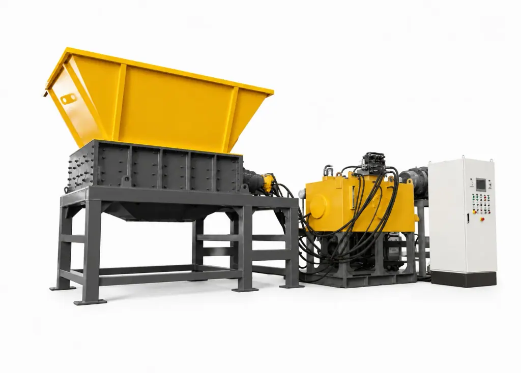
A Hydraulic Shredder serves as the primary shredder in a Waste Tire Granule Line. A low-speed, high-torque hydraulic motor drives the cutters directly, crushing and shearing tire bead wire and thick rubber to reduce bulky tires into smaller shreds.
Radial tires present extreme resistance variations due to high-hardness bead wire and intersecting cord plies. When encountering blockages, mechanical gear drives transfer rigid shocks that break gear teeth or burn out motors. Hydraulic fluid compressibility absorbs these shock loads, making the system suitable for processing thick rubber mixed with heavy and fine wire.
Equipment sizing requires verifying the shredding chamber resistance to transient shock loads and the variable-displacement pump response speed. Power calculations must consider more than average power draw. Engineers must evaluate the seconds required for the main circuit to reach peak pressure and the pressure relief logic during shaft reversals.
| Equipment Type | Feed Material | Process Stage | Key Criteria |
|---|---|---|---|
| Hydraulic Shredder | Whole scrap tires, steel-containing bead bundles | Primary size reduction | Handles shock loads and sudden jamming by adjusting cutting torque via hydraulic pressure variations |
| Downstream Fine Grinder | De-wired rubber chips, shredded rubber chunks | Granulation and final sizing | Requires wire separation upstream, utilizing high-frequency cutting to control final particle geometry |
1. Matching High Shock Loads in Primary Tire Shredding with Hydraulic Drive Characteristics
Resistance jumps significantly when cutter teeth move from tread rubber to high-carbon tire bead wire. When mechanical drives face sudden load spikes, they rely on motor thermal overload or mechanical torque limiters. Frequent chamber shutdowns interrupt feed rates across the entire line.
A Hydraulic Shredder couples the hydraulic motor directly to the rotor shaft. When cutters encounter thick steel wire and pressure spikes, the variable-displacement pump immediately reduces swashplate angle. Rotor speed drops while output torque reaches maximum to shear through the steel, protecting the shaft assembly from rigid impact.
Hydraulic drives offer operational stability where plant transformer capacity is limited. When un-debeaded heavy truck tires enter the chamber, frequent heavy-load starts of electric drives cause grid voltage drops. A hydraulic power unit running continuously with variable adjustment prevents electrical trips, allowing steady feeding via the conveyor.
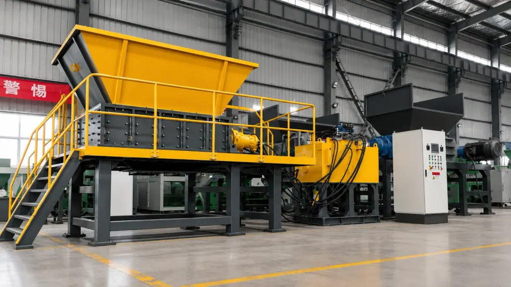
2. Sizing and Calculations for Low-Speed High-Torque Motors and Main Pumps
Sizing the hydraulic drive starts with blade tip linear speed to calculate shaft RPM and required torque. High operating speeds harm rubber shearing. Excessive speed generates frictional heat that melts rubber, coats the cutters, and causes slipping. Lower rotor speeds allow the cutting tips to penetrate the tire casing and shear individual steel cords.
A closed-loop variable piston pump paired with a high-displacement radial piston motor handles heavy-duty tire shredding. When teeth catch on a bead bundle, system pressure reaches rated shearing levels within milliseconds, generating tens of thousands of Newton-meters of torque without a gearbox and eliminating numerous driveline components.
The nominal diameter of the directional and make-up valve manifold is central to circuit calculations. Because scrap tires carry dirt and debris, the shaft reverses frequently to clear jams. A large-bore valve manifold relieves pressure faster to absorb reverse hydraulic spikes, preventing vibration-induced leaks at high-pressure pipe fittings.
3. Wear-Resistant Cutting Chamber Design and Anti-Wrapping Overload Protection Logic
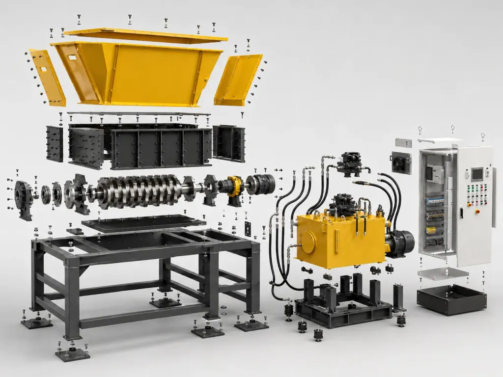
Liberated fine wires migrate along the rotor toward both ends of the chamber. Once wire penetrates bearing seals and degrades the grease, bearings seize within days. The cutting chamber ends require labyrinth deflector rings to form a positive mechanical barrier that protects the bearing housings.
Cutter thickness and tooth geometry govern intake efficiency. When processing whole uncut tires, flat-topped teeth slip, while hooked teeth hook the bead bundle and pull it into the cutting zone. Hook roots must be thick enough to resist lateral thrust, preventing blade deflection and maintaining tight cutting clearances.
The electrical control logic must tie into the main safety relief valve. If hydraulic pressure stays at the relief threshold beyond a set duration, the PLC must stop the machine and alarm. Sustained dumping across the relief valve generates excess heat that degrades hydraulic seals.
FAQ
- What is the primary role of a Hydraulic Shredder in a Waste Tire Granule Line?
- The unit operates at the head of the primary shredding section, reducing whole scrap tires into rubber chips. Using low shaft speeds and high torque, it shears through casings and heavy bead wire to supply uniform feed material to downstream wire separation and secondary grinding stages.
- What drive configurations require verification when procuring a scrap tire Hydraulic Shredder?
- Key checkpoints include the variable pump displacement response time and the working pressure of the radial piston motor. Buyers should also inspect the flow bore of the reversing relief valve manifold, which determines clearing speed during blockages and controls vibration that causes hydraulic line leaks.
- What cutting chamber maintenance is required when processing scrap tires containing dirt and wire?
- Daily maintenance requires inspecting the anti-wrapping seals at both shaft ends to confirm fine steel wire has not entered the bearings. Technicians must also check lateral blade clearances with feeler gauges. Rounded teeth or widened gaps let rubber wedge between cutters, causing abnormal hydraulic pressure rises.