
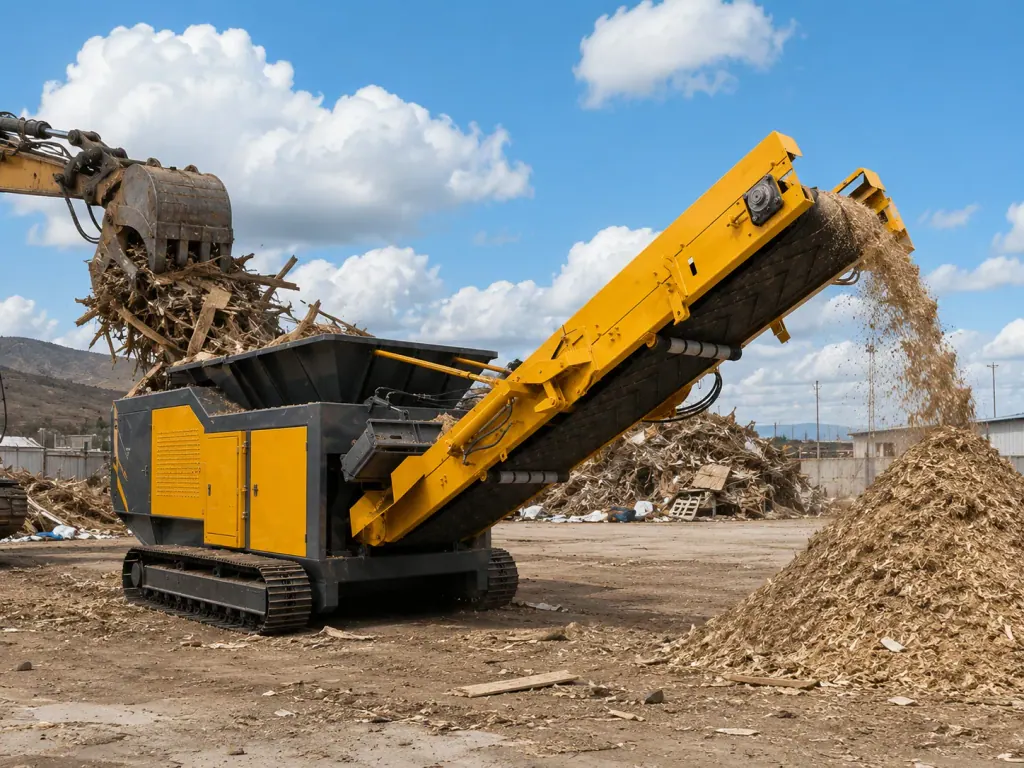
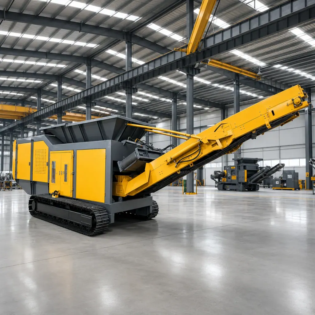
The Mobile Shredder integrates a low-speed, heavy-duty shear assembly onto its chassis. Alloy blades mounted on the rotors use interlocking compression and tearing action to handle primary shredding and volume reduction of scrap cars, industrial structural steel, and oversized mixed metals within a Ferrous Metal Shredding Line.
Selection depends on raw material dispersion and on-site power availability. If scrap sits in multiple stockpiles requiring frequent relocation across working faces, a mobile unit with an integrated chassis eliminates double handling and road transfer costs. Where utility grid capacity is sufficient and processing points remain fixed year-round, stationary workstations provide a logical alternative.
Equipment selection focuses on feed dimensions, target discharge sizing, and the shock load tolerance of the hydraulic drive. The unit delivers a processing capacity of 20-80 t/h, with output size adjustable within a range of 30-200 mm.
| Equipment Configuration Item | Technical Parameters or Selection Range | Operating Condition Sizing Note |
|---|---|---|
| System Processing Capacity | 20-80 t/h | Adjusted based on bulk material density and upstream grapple cycle speed |
| Discharge Sizing Range | 30-200 mm | Adjusted to match downstream Ferrous Metal Shredding Line separation requirements |
1. Material Characteristics in Ferrous Primary Shredding and Chassis Load Sizing
Car bodies, baled sheet metal, and industrial scrap feature irregular geometries and frequently contain thick structural sections. Shear resistance surges within fractions of a second, requiring the frame and chassis to absorb sustained high-frequency vibration and severe dynamic shock.
Relocation frequency and ground bearing capacity dictate the choice of running gear. For soft ground, unpaved scrapyards, or uneven quarry pits, heavy-duty tracked undercarriages distribute ground contact pressure across wide track pads to prevent bogging down. When hauling between smooth concrete pads across longer distances, a wheeled trailer chassis paired with a tractor unit reduces mobilization expenditure.
2. Low-Speed High-Torque Drivetrains and Overload Auto-Reverse Protection
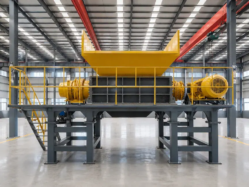
Primary shredding relies on low rotational speed combined with massive torque. When engaging monolithic structural steel or thick-walled pipe, the rotors exert continuous biting torque rather than depending on high-speed kinetic impact.
Site power infrastructure determines the drivetrain type. Remote stockpiles with limited grid access favor diesel-hydraulic systems, where hydraulic motors supply high break-out torque and cushion pressure peaks. Facilities with adequate transformer capacity and cabling access benefit from electric motor drives, cutting operational energy costs per ton.
Hydraulic circuit pressure spikes immediately if dual-shaft alloy cutters meet uncrushable tramp material. The monitoring system detects peak overload pressures and commands the shafts to reverse rotation instantly, dislodging the obstruction before re-engaging to avoid mechanical stall or drivetrain damage.
3. Feed Hopper Specifications and Discharge Conveyor Layouts
Hopper capacity and construction must match upstream loading equipment. When feeding directly via scrap grapples or excavators, heavy wear liners protect the hopper walls against impact damage, and the throat opening must exceed maximum grapple span to prevent material bridging.
Downstream requirements dictate conveyor specifications. If reduced material goes directly to bulk stockpiles, high-angle folding discharge belts stack stockpiles efficiently. When feeding downstream separation stages directly, overband self-cleaning magnetic separators extract ferrous metals while downstream eddy current separators isolate non-ferrous metals and inert debris.
Machine in Action
FAQ
- What types of ferrous scrap can the Mobile Shredder process?
- The machine processes car bodies, industrial scrap steel, and oversized mixed metal scrap, using alloy cutting tools to deliver shearing, compression, and primary volume reduction.
- How is discharge sizing determined across different shredding applications?
- Discharge sizing adjusts between 30-200 mm. If shredded product feeds directly into melting operations or downstream magnetic separation stages, a tighter discharge setting is required. When the goal is simply volume reduction for storage and transport, setting a larger gap maximizes throughput.
- How does the machine react when uncrushable heavy scrap causes a stall?
- Sensors monitor operating load and hydraulic pressure continuously. When overload resistance is encountered, the control system automatically reverses shaft rotation to reposition the material before resuming forward shearing, protecting internal drive components.