
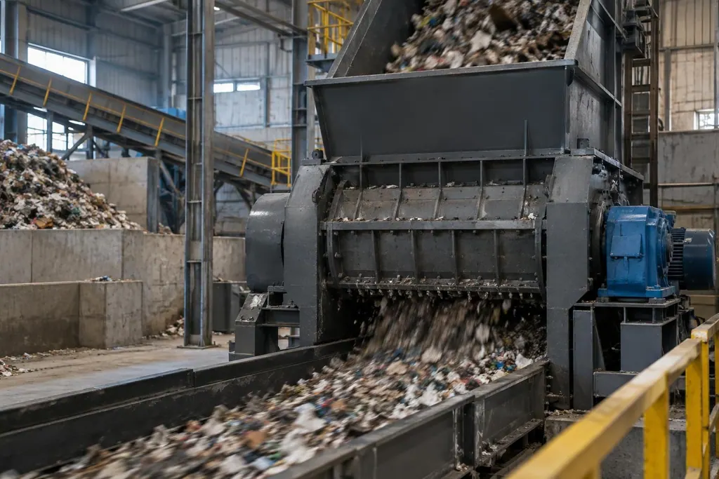
In a Ferrous Metal Shredding Line, the Hammer Shredder uses a high-speed rotor to drive swinging hammers that strike, tear, and densify scrap steel, stripping paint, separating contaminants, and reducing material volume.
Processing heavy scrap exposes the rotor assembly and crushing chamber to cyclic shock loads. Unnoticed wear part failure or loose fasteners can lead to out-of-spec discharge and higher power draw, or cause hammer loss, rotor jams, and shaft breakage.
Daily inspections require maintenance staff to assess the swinging hammer assembly, stationary liners, and drive bearings during both static shutdowns and no-load test runs.
| Inspection Point | Primary Inspection Items | Condition Assessment and Action Criteria |
|---|---|---|
| Hammer assembly | Surface wear and rotor dynamic balance | Reverse in pairs when striking edges round off or chip; avoid single-piece replacement to preserve balance |
| Hammer pins and fasteners | Pin straightness and thread locking integrity | Scrap immediately if stepped grooves or bends appear; verify bolt torque and locking hardware |
| Chamber liners | Crack growth, loosening, and geometry loss | Replace cracked or worn-through sections entirely; replace and retorque sheared fasteners |
| Bottom grate bars | Bar spacing and outward deformation | Re-align gaps if deformation causes material recirculation; replace once wear limits are exceeded |
| Main bearing housings | Operating temperature rise, vibration, and noise | Check lubrication and raceways if heat rises sharply; rebalance rotor if low-frequency vibration increases |
Inspection Procedures for Hammer and Pin Wear and Fastening Integrity
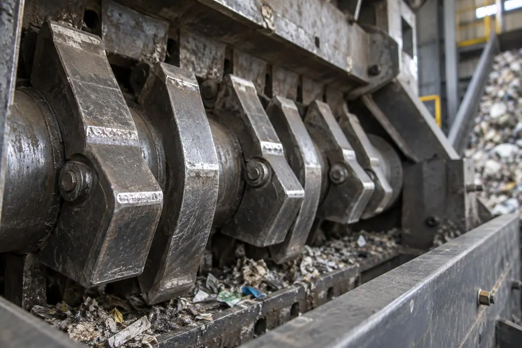
After isolating and locking out power, open the service doors to inspect the hammer face and edge profiles. When the working face develops an excessive radius, or deep impact gouges form on the tip, reverse the hammer position or replace the full set. Significant mass loss on an individual hammer disrupts rotor balance and produces heavy machine vibration. The decision to reverse or replace depends on rotor vibration severity and physical hammer deformation: if a flat striking reference remains, flip the hammer; if wear has reached the pin bore, scrap the entire group.
When reversing or replacing hammers, do not replace single units randomly. Always install matched pairs symmetrically about the rotor centerline to maintain uniform circumference mass. Measure hammer pin working sections with calipers for stepped wear depth and bending. Any pin with visible step ridges or localized oval deformation must be scrapped immediately, eliminating the risk of brittle fracture under impact loads.
Inspect pin retaining plates and lock bolts on each end after assembly. Verify fastener torque with a calibrated wrench, check lock washers for cracks, and verify each hammer swings freely on its pin without binding from entrapped scrap or deformed bushings.
Evaluating Wear and Deformation on Liners and Grate Bars
High-manganese or alloy liners inside the chamber endure high-velocity metal impacts and continuous material scrubbing. When inspecting toothed liners, look for through-thickness longitudinal cracks or sheared countersunk bolts. Shut down the machine to replace broken hardware or worn castings before loose liners drop into the chamber and jam the rotor.
Discharge grates and bar gaps control final product size. If shredded fractions coarsen or loose non-densified material increases, measure bar center gaps and leading-edge wear. Bars bent outward by heavy tramp items narrow sections of the discharge path, causing material build-up and increasing chamber grinding wear.
Decide whether to adjust or flip liners based on side-wall clearance uniformity and scrap balling density. If worn liner faces cause material to glance away from the crushing zone and increase chamber retention time, place shims behind the wear plates. Once the impact angle is lost completely, install fresh liners to restore the internal crushing geometry.
Troubleshooting Rotor Bearing Temperature Rise and Vibration
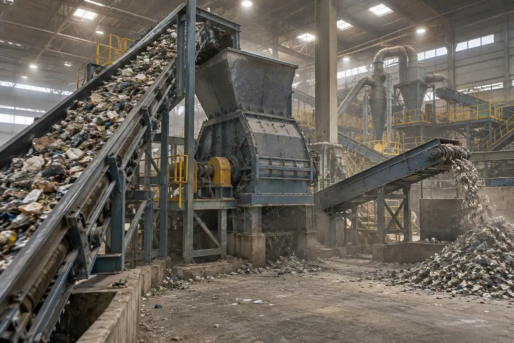
During no-load runs and production in the Ferrous Metal Shredding Line, inspect the main bearing housings on both ends with contact thermometers and vibration pens. A steep temperature rise during steady operation, or sustained high surface heat, points to degraded grease, over-greasing that traps heat, or spalled internal rollers.
Diagnose vibration issues from the outside inward. First inspect shaft alignment at the coupling between motor, gearbox, and rotor shaft, checking the elastic elements for damage. Retorque the bearing foundation bolts and check structural base welds. If low-frequency runout persists after eliminating external looseness, rotor dynamic balance is compromised, typically caused by uneven rotor disc rim wear or an unseated hammer.
A dull, continuous pounding inside the housing requires stopping the feed conveyor immediately. Let the rotor coast to clear loose scrap, then open the chamber to check for unshreddable tramp iron wedged between hammer discs. Inspect rotor spacers and side liners for contact gouges to rule out shaft deflection or axial drift. Use the severity of foreign object jams and contact wear depths to decide between on-site debris removal or shaft pull-down to correct axial play.
FAQ
- When should Hammer Shredder hammers be reversed or replaced?
- Reverse or replace hammers when the striking face rounds off, lowering shredding efficiency, or when a hammer chips. Always replace parts in diametrically opposed pairs relative to the rotor center to prevent dynamic unbalance and severe machine vibration.
- How can operators assess liner and grate bar wear from the shredded discharge?
- Enlarged scrap bundles or poor paint and rust removal along the Ferrous Metal Shredding Line indicate that liner teeth have worn flat or grate bar openings have widened. Stop the unit to measure grate bar openings and verify whether breaker liners still maintain proper scrap trajectory angles.
- Which mechanical areas should be checked first when bearing housing vibration exceeds limits?
- Check foundation bolts and base structural fasteners for looseness first, then inspect coupling alignment. If external mountings are intact, open the upper housing to check hammer wear uniformity around the rotor circumference, ruling out material build-up, trapped tramp metal, or asymmetrical hammer mass loss that disrupts dynamic balance.