
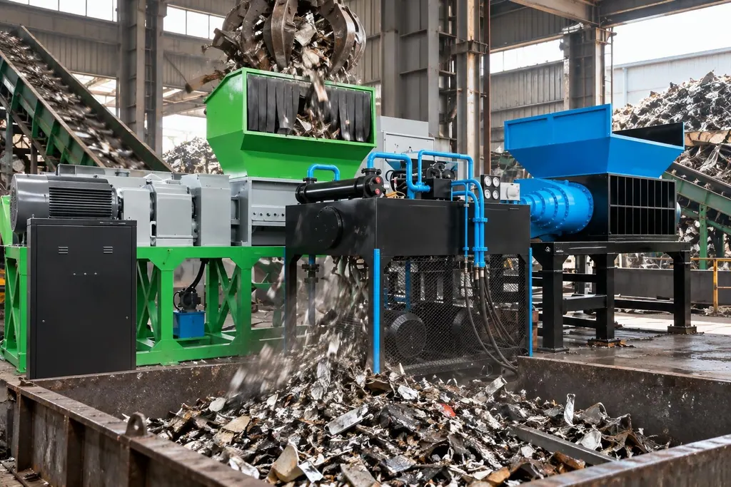
A Hydraulic Shredder is used primarily for primary coarse reduction of ferrous scrap. Low-speed, high-torque hydraulic motors directly drive the knife shafts, relying on alloy blades to shear, crush, and compact bulky structural scrap and car bodies.
When heavy steel plate and high-rebound structural sections enter together, mechanical gearboxes risk tooth breakage under sudden stall conditions. A hydraulic drive transmits torque directly via fluid pressure. If an unshreddable solid object blocks the chamber or causes an instantaneous overload, the circuit relief valve vents pressure quickly to protect the shafts and machine housing.
The proportion of uncrushables and the magnitude of shock peaks dictate the required configuration. If the feed contains thick, unprepared metal parts, the machine requires variable displacement control and an automatic reversal sequence to eliminate manual clearing.
| Configuration Type | Drive and Power Characteristics | Target Scrap Material | Selection Criteria |
|---|---|---|---|
| Hydraulic Double-Shaft Shredder | Direct-drive hydraulic motor, low speed, high torque, fluid relief protection | Car bodies, mixed heavy scrap, baled metal | Feed contains unknown heavy solids, requires hydraulic circuit to dampen dynamic shock and avoid shaft failure |
| Mechanical Gear-Driven Shredder | Electric motor paired with hardened industrial gearbox, rigid mechanical transmission | Light gauge sheet, tinplate, small uniform scrap bales | Material thickness is uniform with zero unshreddable solid inclusions, operates at fixed operating speed |
1. Mixed Scrap Processing Conditions and Hydraulic Drive Characteristics
Feeding car bodies, heavy sections, and high-yield plate together creates uneven cutting forces across the chamber. Mechanical gearboxes have no damping buffer to absorb these impact loads.
Hydraulic pumps deliver high-pressure oil directly to low-speed, high-torque motors coupled to the cutter shafts. If the blades bind against an uncrushable object, the oil dumps back to tank through the relief valve, preventing gear damage.
The presence of unshreddable solid components determines the drive selection. If the feed is uniformly thin sheet, a mechanical drive offers lower capital cost. When heavy I-beams or solid shafts enter the mix, a direct hydraulic drive is required to let the oil cushion dynamic shocks.
2. Low-Speed High-Torque Delivery and Anti-Jam Configurations
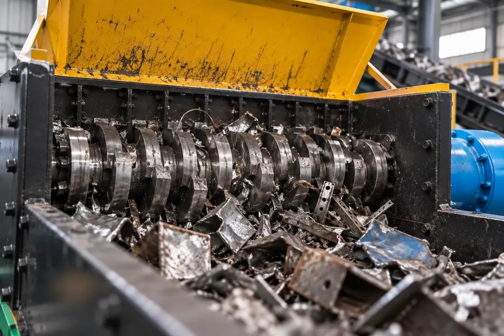
Hydraulic motors maintain rated torque near stall conditions or at extremely low rotational speeds. As the cutting teeth penetrate deep into scrap bundles and shaft speed drops under load, shearing force does not fade, allowing the shafts to complete the cut.
Pressure sensors work with the PLC to execute anti-jam routines. When shearing resistance pushes circuit pressure beyond the trip threshold, the directional valve shifts instantly to reverse the shafts, dislodge the lodged piece, and return to forward shredding.
Material yield strength and thickness define the reversal stroke. Baled thin sheet with high springback requires a short, rapid reversal cycle to maintain throughput. Heavy plate scrap requires a longer reversal stroke to clear the cutting zone, which avoids re-jamming in place and prevents oil overheating.
3. Hydraulic Power Unit Sizing and Rotor Configurations
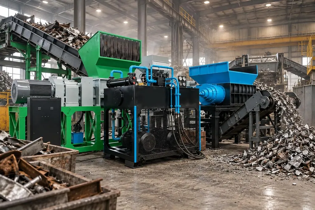
A separate hydraulic power unit drives the shredder, using constant-power variable displacement pumps to balance flow and pressure against the load. Under light, thin feed, the pump delivers higher displacement to accelerate shaft speed for intake. When heavy material enters, displacement drops and system pressure increases to drive through the cut at low speed.
Intake performance depends on rotor geometry and knife profile. Processing loose scrap such as baled goods or car shells requires hooked teeth to grab the bulk. Processing tangled tubing and mixed wire requires specific blade thicknesses and cutting bevels that resist wear under cyclic loading.
Downstream specifications determine the discharge configuration. Coarse-shredded scrap moves directly to separation, meaning the discharge belt must use cut-resistant belting and work alongside an overbelt or drum magnetic separator to extract ferrous fractions.
FAQ
- What is the operational advantage of a Hydraulic Shredder over an electric mechanical-gearbox shredder in heavy scrap duty?
- A hydraulic motor maintains peak torque at near-stall shaft speeds, while the hydraulic safety circuit dumps excess pressure during severe overload. This fluid-based release removes rigid mechanical shock, protecting shafts from snapping and gears from stripping teeth.
- How should the anti-jam reversal sequence be set for mixed scrap?
- Pressure transmitters monitor line pressure in the main loop. Once shearing resistance exceeds the set limit, the controller activates the directional valve to reverse the shafts, clear the lodged mass, and shift back to forward rotation. Thicker feeds require longer reversal travel, while thinner fractions run better on shorter cycles to preserve capacity.
- What upstream and downstream equipment is typically paired with a Hydraulic Shredder in a Ferrous Metal Shredding Line?
- Feed setups typically rely on heavy-duty apron feeders to absorb crane drops, while the discharge connects to reinforced rip-proof belt conveyors paired with overbelt or drum magnetic separators to recover ferrous metal.